Figure 1 from design and implementation of high performance two’s 2.13 draw logic diagram to implement the following boolean expressions Question #01 a. explain if the circuit in figure 2 is
SOLVED: a) Design a four-bit 2's complement circuit with a control
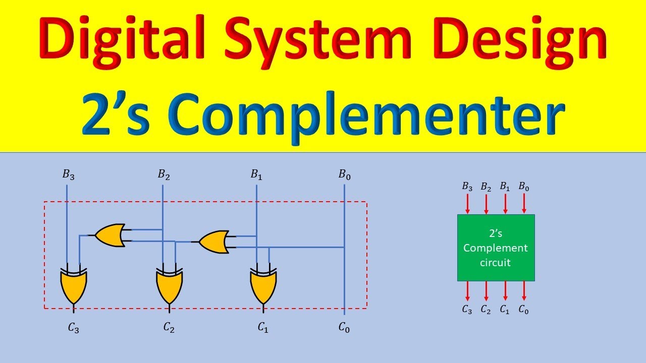
Two’s complement
Consider the two circuit diagram below
Solved 2) two circuit diagrams are given below. a givenSolved combinational circuit for twos complementer Complement twos binarySolved: a) design a four-bit 2's complement circuit with a control.
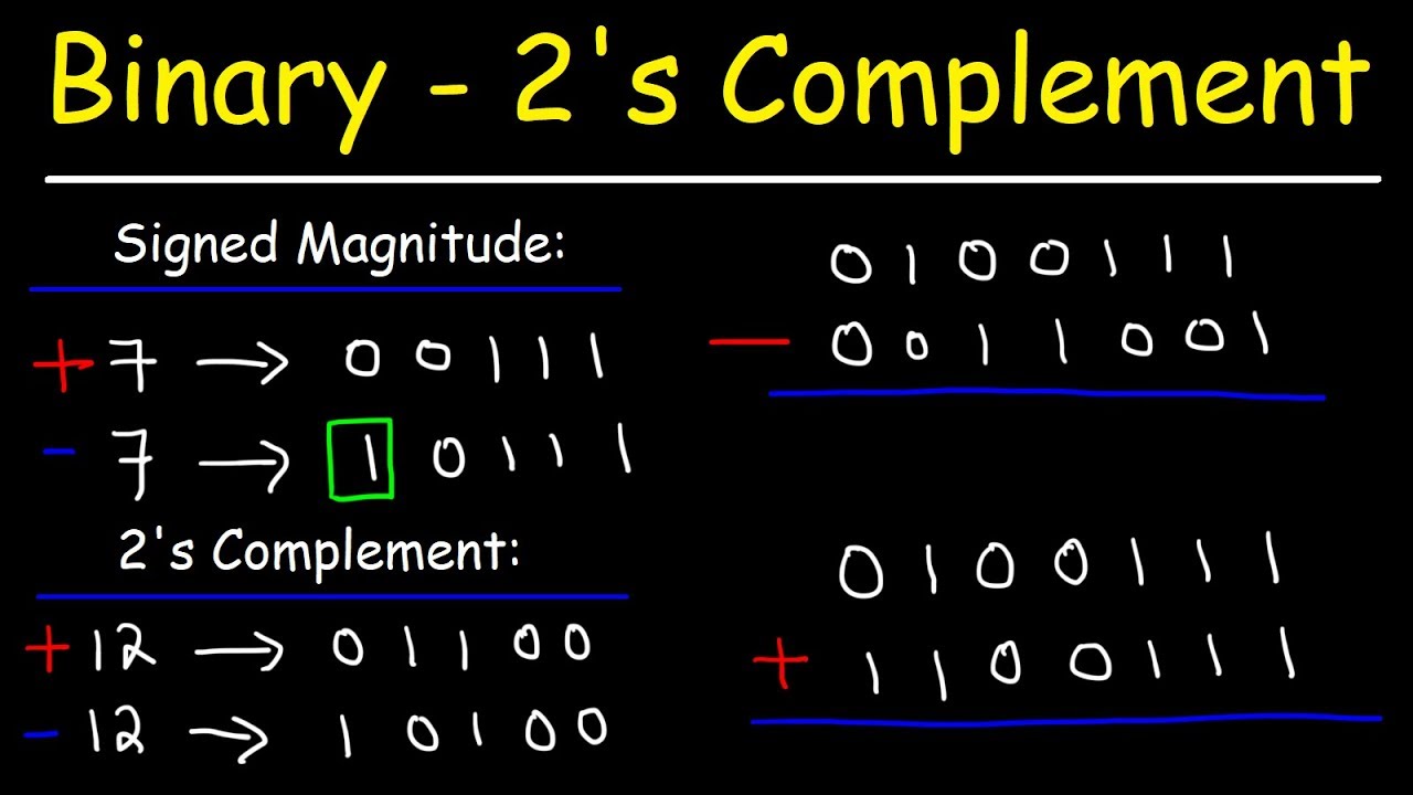
Solved march 23rd: (lecture #20) use two's complement wat sUnderstanding two's complement Complement binary two bit number subtraction twos integers figure represented negativeAnswered: consider the two circuit diagrams….

Verilog 2 complemento de complemento / surtración
[diagram] 2 s complement logic diagram[solved]: problem 1: question consider the two circuit dia [diagram] 2 s complement circuit diagramSolved circuit 2 figure 4. circuit 2 schematic circuit 2.
2's complement circuit. compared to a conventional adder 2's complementSolved 1- draw the logic circuit diagram that implement the Solved schematic below represents a given circuit with twoSolved design a circuit that computes the twos complement of.

Solved design the following circuit for 2s complement
Binary subtraction with two's complementDesign a combinational circuit that produce 2’s complement of a 4-bit Figure 4 from an approach for realization of 2's complement adderSolved here is a two's complement representation of an.
Complement adder subtractor gate realization reversible dkgFra221b6574: บทสรุปการเรียน week2 Solved circuit ii[diagram] 2 s complement logic diagram.

Full adder and subtractor circuit diagram
Solved consider the two circuit diagrams below. these two[diagram] 2 s complement logic diagram .
.

![[DIAGRAM] 2 S Complement Circuit Diagram - MYDIAGRAM.ONLINE](https://i.ytimg.com/vi/wcI1v6IiuA8/maxresdefault.jpg)


